STP operation
STP is the Layer 2 loop prevention mechanism: it keeps physical path redundancy while making sure only one path to each network segment is active at a time. It’s on by default on Cisco Catalyst switches.
The behavior in three points:
- Switches communicate using BPDUs (bridge protocol data units).
- Certain ports are forced into a blocked state, where they don’t listen to, forward, or flood data frames.
- If an active segment fails, STP activates a previously inactive path (blocked port moves to forwarding), if one exists.
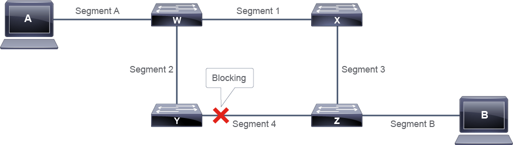
Terminology note: the original STP was written for Ethernet bridges (802.1D, obsolete hardware now), so the terms still say “bridge” even though everything running it today is a switch.
The bridge ID
STP’s reference point is the root bridge, the logical center of the spanning tree topology. Every path not needed to reach the root bridge gets blocked. The root is chosen by election, based on the lowest bridge ID (BID).
In original STP the BID is 64 bits: a 16-bit bridge priority followed by the 48-bit MAC address. Priority ranges 0-65535, default 32768 on Cisco switches.

The evolved variants (PVST+, RSTP, MSTP) split the old priority field in two: a 4-bit bridge priority and a 12-bit Extended System ID that carries the VLAN ID or instance number. Command outputs show either the combined 16-bit value, or a priority that only moves in increments of 4096 (since the lower 12 bits are zero) plus the extended system ID. 0 decimal is 0000000000000000 binary; 61440 is 1111000000000000.
The algorithm
- All interfaces on all switches start in blocked mode.
- The switches elect a root bridge: lowest BID wins. Same priority everywhere means the lowest MAC address wins. One root per network in original STP, one per VLAN in PVST+.
- Each nonroot switch determines its root port: the port with the lowest root path cost (cumulative STP cost of all links to the root bridge).
- On each segment, a designated port is selected, again by lowest root path cost. On the root bridge, every port is designated. One designated port per segment.
- Root ports and designated ports transition to forwarding; everything else (nondesignated ports) stays blocking.
Don’t leave the election up to chance: the lowest MAC winning by
default means the oldest switch often becomes root. Configure the
priority. spanning-tree vlan X root primary drops the default by
increments of 4096 (secondary drops it by one increment, primary by
two), or set it directly with the priority command: 0 for the
primary, 4096 for the secondary. If the primary root fails, the
configured secondary takes over.
Path costs
Cost is based on link speed: higher bandwidth, lower cost. It can be changed manually.
| Data rate | 802.1D-1998 (short) | 802.1D-2004 (long) |
|---|---|---|
| 4 Mbps | 250 | 5,000,000 |
| 10 Mbps | 100 | 2,000,000 |
| 16 Mbps | 62 | 1,250,000 |
| 100 Mbps | 19 | 200,000 |
| 1 Gbps | 4 | 20,000 |
| 2 Gbps | 3 | 10,000 |
| 10 Gbps | 2 | 2,000 |
Catalyst switches running PVST+ or Rapid PVST use the short method out of the box; MST and some non-Catalyst gear (Nexus) can use the long method.
Port roles
- Root port: nonroot bridges only. Best path toward the root; forwards traffic toward the root bridge and populates the MAC address table for its segment. One per switch (per VLAN in PVST+).
- Designated port: root and nonroot bridges. Receives and forwards frames toward the root as needed; populates the MAC address table. One per segment, chosen by election when multiple switches share the segment. All root bridge ports are designated.
- Nondesignated port: blocking data frames, not populating the MAC address table.
- Disabled port: shut down.
Election walkthrough
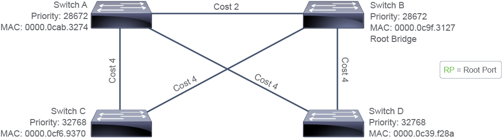
Every switch initially claims to be root, sending BPDUs with the Root ID field set to its own BID. When a switch receives a BPDU with a lower root ID than the one it has recorded, it adopts the lower value and starts advertising it. Eventually everyone converges on the lowest BID in the network.
Here switch B wins: A and B share priority 28672, but B has the lower MAC address.
Each nonroot switch then marks the port receiving the root’s BPDUs as its root port. With BPDUs arriving on multiple ports, the tie-break order is:
- Lowest root path cost.
- Lowest upstream BID.
- Lowest port ID in the received BPDU (both ports go to the same upstream switch).
A, C, and D all pick their directly connected port to B: those are the lowest-cost paths. From D’s perspective, the direct link is cost 4 and the way around is 6, so the direct port wins.
Designated ports work the same way: each switch on a segment claims its port is designated, and when it sees a neighbor’s BPDU with better values (root path cost, then BID, then port ID), it stops transmitting BPDUs there and marks the port nondesignated. All of B’s ports are designated; A’s ports toward C and D are designated because A has the lower root path cost on those segments.
Two loops in this topology, so two ports block: the nondesignated port on C and the one on D, the ones not directly connected to B.
Convergence details
The steps don’t run in a neat sequence. Every switch runs them in parallel, adjusting its selections as new BPDUs arrive, until the whole network settles on a consistent view. Once stable, only designated ports transmit BPDUs (every 2 seconds), but blocking ports keep listening. A blocking port that stops hearing BPDUs begins transitioning to forwarding.
Original and rapid STP run the same decision algorithm; the difference is the transition. Classic 802.1D takes 30 seconds to move a port from blocking to forwarding. RSTP (where blocking is called discarding) can do it in under a second.
The weakness: all traffic traverses the root bridge. C to D goes through B even though a direct-ish path exists. STP builds one shortest-path tree per topology, calculated from the single root. Compare OSPF, where every router is its own root and calculates its own SPF tree, so there’s one tree per router.
PVST+ and load sharing
PVST+ runs a separate spanning tree instance per VLAN, identified by the extended system ID. That’s what makes load sharing possible: with two distribution switches above a pair of access switches, make one the root for VLANs 1-50 and the other the root for VLANs 51-100. Each VLAN group forwards up its own uplinks and blocks the others, so both uplinks carry traffic instead of one sitting idle.